How to Build a Spark Gap Tesla Coil
A 15 kV neon sign transformer, 17 capacitors, and two coils.
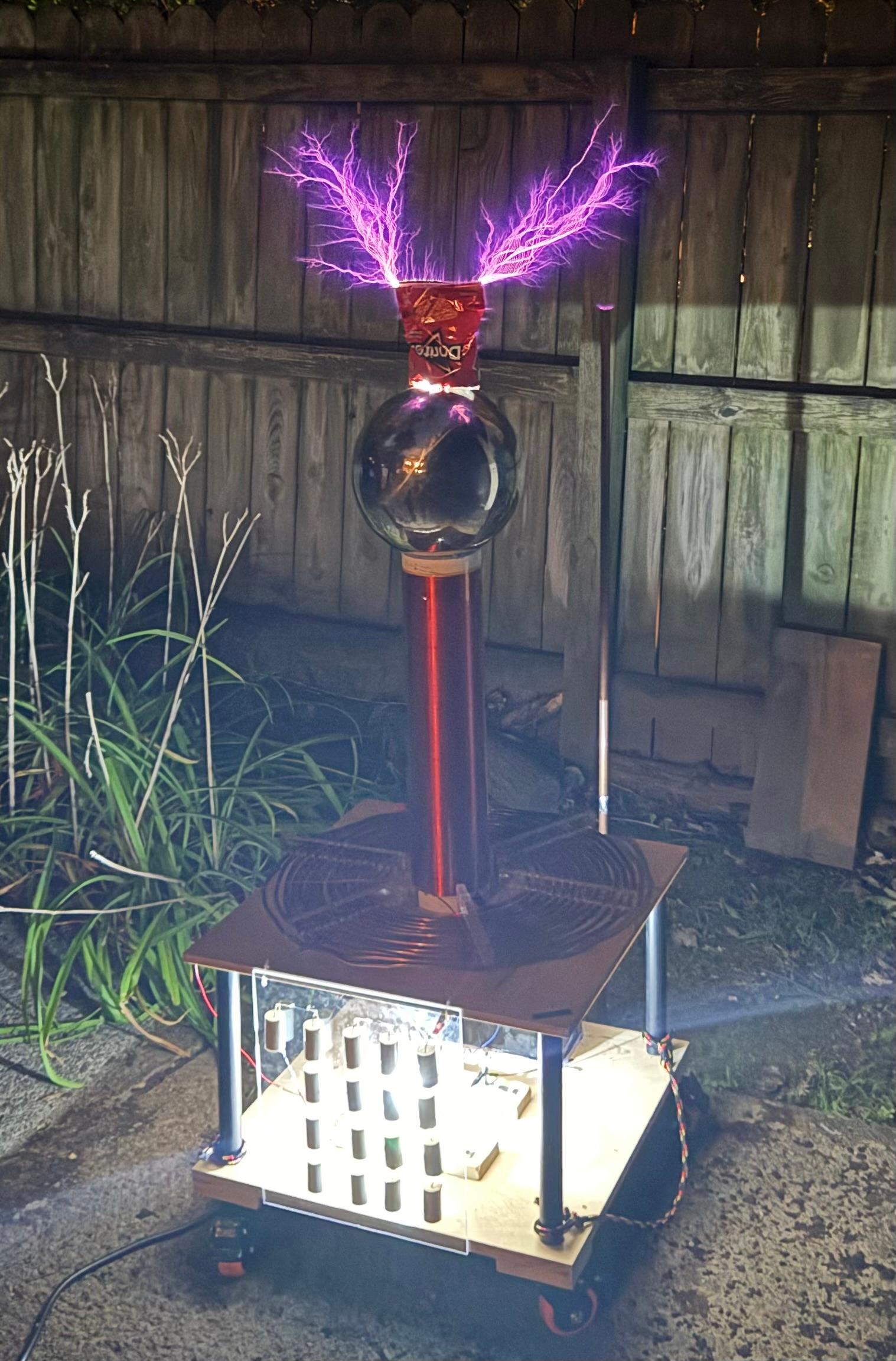
A few friends and I built a spark gap Tesla coil in the spring of 2025, around a 15 kV, 30 mA neon sign transformer. I was flexible on budget going in (willing to go bigger if that meant a cooler zap), and solid state came up, but I was definitely cool with spark gap first. It was the design we were confident we could finish in a few weeks.
Safety First#
A neon sign transformer can kill you. Our rule while it ran: anyone within 3 feet could die. From our reading, a good list of safety things to keep in mind:
- Capacitors remaining charged after disconnecting from power. Discharge the bank before touching anything.
- Drawing sparks onto things. Use a long insulated stick and keep it completely dry. Ours was 2 feet, too short. Moist or wet skin can apparently drop your resistance by 10x to 100x, which… whoa.
- Ozone. Run it outside.
- Some emitted frequencies are dangerous to people with cardiac implants. Public demos: people about 6 feet back, anyone with an implant 12 feet.
How It Works#
Two circuits ringing at the same frequency:
- NST: steps wall power up to 15 kV and charges the primary capacitor
- Spark gap: fires once the capacitor is charged enough, connecting it to the primary coil
- Capacitor + primary coil: an LC circuit, ringing at a few hundred kilohertz
- Primary and secondary coils: a few turns of thick copper tubing under ~1,000 turns of thin wire, tuned to the same frequency. Energy sloshes from one to the other over a few cycles and the voltage climbs way past 15 kV
- Top load: metal, on top of the secondary, holds that charge until the air around it breaks down into sparks
Richie Burnett's explanation (opens in new tab) is the best written overview of what's happening in the circuit that we found.
Parts and Cost#
- Transformer. A Transco Poly-Lok iron core NST, 120 V in, 15 kV and 30 mA out, $80 from a neon sign shop, which is cheap for these. It died after a few runs, so we ended up getting two more 15 kV, 30 mA units.
- Capacitors. 20 CDE 942C20P15K-F film capacitors, 0.15 µF and 2,000 V each, for $197 with shipping, sales tax, and tariff. We used 17 of them.
- Base. A two-level wooden cart on casters, about $125 in materials.
- Variac. For setting the safety gap, see Step 3.
- Coils and top load. Copper tubing, magnet wire on a plastic form, and a metal sphere. More on each of these below.
Step 1: Get a Transformer#
Look for an old iron core NST. Newer ones have a ground fault circuit interrupter (GFCI), which makes them safer but useless to Tesla coils. It stops the NST when the current in the hot and neutral wires seems off. Neon sign shops sometimes have old ones sitting around. When we called one and asked for an old iron core NST, the guy asked what on earth we wanted it for, so we just told him the truth. He had one that had been sitting there for a very long time, and he tested it with us and it worked great.
A couple things on the nameplate tripped us up when we first saw them, but they're normal:
- 120 V, 3.8 A in, and 15,000 V, 30 mA out. 15,000 / 120 = 125 and 3.8 / 0.03 ≈ 127, so the ratio checks out.
- You'll see a "250 W" number there, less than the 456 VA it draws (120 V × 3.8 A). That's related to the power factor, about 0.55. Normal power factor NSTs draw more than they use, just sloshing current back and forth from the socket, but it's negligible money-wise. From what I read it's a few cents for a whole hour of running.
- "Short circuit current: 30 mA". That's the max and also the normal output. Even old NSTs without GFCI are current limited, so if they short you still only get about 30 mA. Forgiving supply.
- 3.8 A in. Max draw most US sockets can handle is 15 A, so 3.8 A is very typical for home use, which makes sense since these power neon signs that are on all the time.
Step 2: Size the Capacitor Bank#
It took some reading to figure out how people pick capacitors. The capacitor that resonates with the NST at 60 Hz:
C = I / (2π · f · V) = 0.03 / (2π · 60 · 15,000) ≈ 5.3 nF
Going a bit bigger keeps the cap and NST off exact resonance, where they'd drive each other to destructive voltages. Our target was 8.4 nF.
There's a 15 kV, 30 mA build we took note of because the sparks look great, the build looks simple, and we would have been very pleased with a result like that. That said, he blew up one of his capacitors. From his comment: "I'm running these caps way over what they're rated for because I didn't take the peak voltage of the NST into consideration. They end up seeing 3.5kV across each one." For a 15 kV NST the peak is 15 kV × √2 ≈ 21 kV, plus spikes when the gap fires.
So: a multi-mini capacitor (MMC), which is just strings of identical capacitors in series. Series divides the capacitance and adds up the voltage ratings. With 150 nF, 2 kV capacitors:
- 15 in series: 10 nF, 30 kV
- 16 in series: 9.4 nF, 32 kV
- 17 in series: 8.8 nF, 34 kV
- 20 in series: 7.5 nF, 40 kV
We got 20 so we could try multiple different total values, and used a single string of 17: 8.8 nF at 34 kV.
- Pulse-rated polypropylene film capacitors. This list (opens in new tab) of recommended ones is old but very trustworthy. The beefiest one on it was also the cheapest for us.
- A bleeder resistor across each capacitor drains the bank after power off.
Step 3: Protect the Transformer#
The usual protection is a Terry filter between the NST and the rest of the circuit: resistors, small capacitors to ground, MOVs, and a safety gap. Our take: it's a cheap insurance convention, but there's not a lot of experimental data, and NSTs seem to fail in Tesla coils all the time even with the full Terry filter. Our first NST had no protection and died after a few runs.
For the replacements:
- Safety gap across the NST output, set to fire just above its normal voltage
- Variac to set it with precision (and a variac sounded more fun anyway)
- Turn the input voltage up slowly, and adjust the gap until it just starts sparking at the top of the NST's range
Step 4: Wire the Primary Circuit#
- Spark gap across the NST output
- Capacitor bank + primary coil in series, also across the gap
- When the gap fires it closes the capacitor and primary into a loop, keeping the high frequency ringing out of the NST
Spark gap options we saw: two regular heavy bolts, parallel copper tubes, ball bearings on the ends of screws. Screws make the gap easy to adjust.
The primary is a flat spiral of copper tubing in acrylic mounts. We drilled ~90 holes into the mounts and threaded the tubing through. The bit we first bought was 9/32, too tight, so we went to 10/32 aka 5/16 and widened them with a right angle drill attachment. Make yours slightly bigger than the tubing from the start.
- Epoxy the mounts to the base
- Movable clip on the primary, since moving it is how you tune
Step 5: Wind the Secondary#
Wind about a thousand turns of magnet wire on a plastic form, side by side with no gaps or overlaps. We built a motorized rig to turn the form. As a reference, one design for a 15 kV, 30 mA NST uses 972 turns of 24 AWG on a 4.4 inch form, wound 22 inches high.
Epoxy the secondary to the base. Ours is solid enough to lift the whole coil by the tower. The bottom of the winding goes to ground, ideally a copper pipe driven into the earth rather than the house wiring.
Step 6: Add the Top Load#
Usually a toroid, but a metal sphere works. We tried three sizes, and the big 12 inch sphere didn't do much more than the medium one. Connect it to the top of the winding.
Step 7: Tune It#
No oscilloscope needed:
- Primary tap a few turns from the center
- Run it briefly
- Power down, discharge the bank
- Move the tap and repeat
Longest sparks = primary and secondary ringing at the same frequency.
Running It#
- Run it at night. Sparks are hard to see in daylight.
- Take long exposure photos of the top load (at least iPhones can do this). They catch every spark at once, like the one at the top.
- A fluorescent tube held near the coil lights up with no wires.
We took ours to a summer festival, where people lined up for over half an hour and kids got to see that you can just build things.
Further Reading#
- Tesla coil design guide (opens in new tab), including the sample design for a 15 kV, 30 mA NST
- JavaTC (opens in new tab), a calculator for estimating a design
- Deep Fried Neon's design pages (opens in new tab)
- Terry filters (opens in new tab) and safety gaps (opens in new tab)
- Neon sign transformers as power supplies (opens in new tab)
- The Zeus Tesla coil (opens in new tab), for the physics of every component